
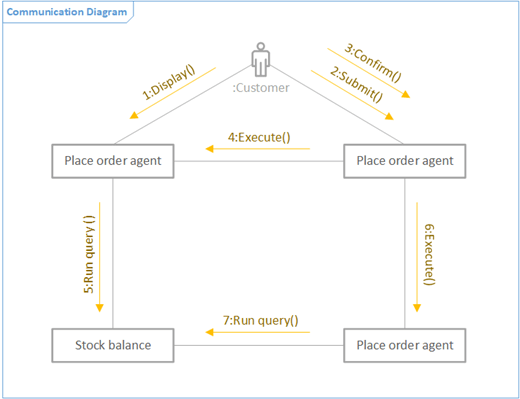
You can create a UML Communication diagram to show the interactions between lifelines that use sequenced messages in a free-form arrangement. First, you open the UML Communication template and pick one of the four template options. Then the UML Communication stencil appears, along with shapes that conform to the UML 2.5 standard.
Note: The UML Communication stencil is only available if you are a Visio Plan 2 subscriber. If you have a subscription, make sure you have the latest version of Visio.
Start a communication diagram
-
Start Visio. Or if you have a file open already, click File > New.
-
Go to Categories > Software and Database > UML Communication.
-
Select the blank template or one of the three starter diagrams. If you want to represent collaboration of lifelines by showing interactions between lifelines, make sure to choose the starter diagram in the lower-left corner.
-
Click Create.
-
You should see the Shapes window next to the diagram. If you don’t see it, go to View > Task Panes and make sure that Shapes is selected. If you still don’t see it, click the Expand the Shapes window button

-
On the View tab, make sure the check box next to Connection Points is selected. This will make connection points appear when you start connecting shapes.
-
Now, drag shapes you want to include in your diagram from the Shapes window to the page. To rename text labels, double-click the labels.
Note: Creating and editing UML diagrams on Visio for the web requires a Visio Plan 1 or Visio Plan 2 license, which is purchased separately from Microsoft 365. For more information, contact your Microsoft 365 admin. If your admin has turned on "self-service purchasing," you can buy a license for Visio yourself. For more details, see Self-service purchase FAQ.
Start a communication diagram
-
Open Visio for the web.
-
Near the upper right, select More templates.
-
In the Gallery, scroll down to the UML Communication row.
The first item in the row represents a blank template plus the companion stencil. The other items in the row are sample diagrams that have some shapes already drawn to help you get started quickly.
-
Click any item to see a larger preview.
-
When you find the diagram you want to use, click its Create button.
The new diagram, with the related stencil, opens in your browser.
Actor and lifeline shapes
When to use
-
Drag the Actor shape to the page to represent the role of a user or an external system.
-
Drag the Lifeline shape to the page for each named element that represents an individual participant.
Interactions between lifelines as messages
Step 1
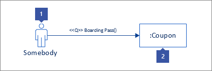
Drag a message shape to the page, and glue one end to a connection point on another shape. You know it’s glued when there’s a green square around the connection point.
Step 2
Do the same for the other end of the message so that it is also glued to a connection point. You know it’s glued when there’s a green highlight around the point.
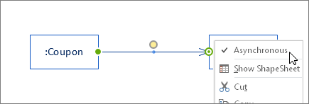
Step 3
If you want the message to be asynchronous, right click and choose Asynchronous. Doing that will change the closed arrowhead to an open one.
Collaboration of lifelines by showing interactions between lifelines
Overview
-
First connect lifelines with the Connector Tool.
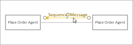
-
Then, use the Message and Return Message shapes to show interactions between lifelines.
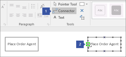
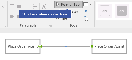
Step 1
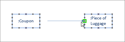
On the Home tab, click the Connector Tool (1). Hover over one of the connection points of a lifeline shape until you see a green highlight (2).
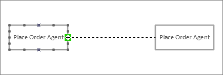
Step 2
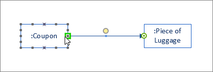
Click and drag from the green highlight to a connection point on another lifeline shape until you see a highlight like this.
Step 3
Click the Pointer Tool when you are done connecting the lifeline shapes.
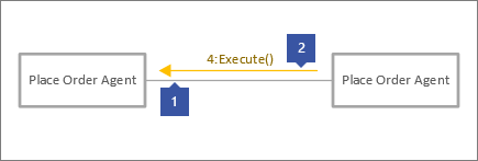
Step 4
Drag another message shape so that it is parallel to the other line.
Tips for connectors
Straighten connectors
If a connector is taking too many turns, right-click it, and then click Straight Connector.
Change connector type
You can change a connector type. For example, you can change from an Association to a Directed Association. Right-click the connector, and then click Set Connector Type.
Make dynamic connections instead of point connections
If you anticipate moving shapes a lot, consider making a dynamic connection instead of a point connection.
Move or rotate text on connectors
Most likely you’ll need to rotate or move text on your connector lines. Here’s how to do that:
-
Click an empty area of the page to deselect anything that may be selected.
-
On the Home tab, in the Tools group, click the Text Block tool

-
Click the connector that has text your want to rotate or move.
-
Drag the text block to move it, or rotate it using the Rotation Handle

-
When you’re done, click the Pointer Tool button

After you switch back to the Pointer Tool button
See Also
Create a UML component diagram


