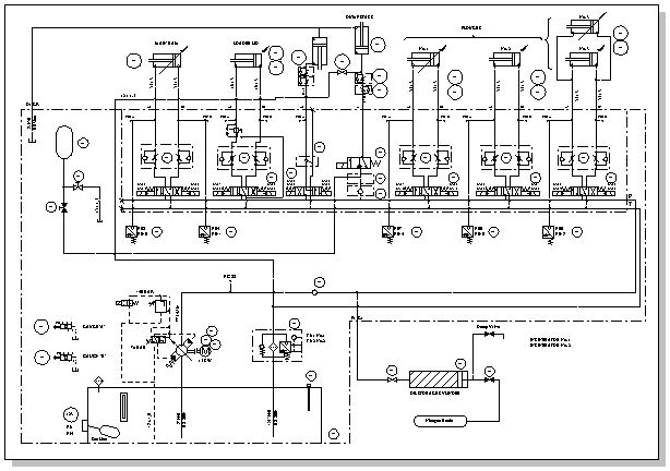
Create fluid power diagrams in Visio Professional or Visio Plan 2 to document hydraulic or pneumatic control systems, such as those used in factory automation systems, heavy machinery, or automobile suspension systems.
-
Click Templates > Engineering > Fluid Power > Create.
This drawing type opens an unscaled drawing page in landscape orientation
-
Drag equipment and valve shapes onto the drawing page.
You can configure many shapes by right-clicking them.
-
Connect components using the Connector tool
Use the Connector tool
-
On the Home tab, in the Tools group, click
-
Drag from a connection point on the first shape to a connection point on the second shape.
For more information on using connectors, see Add connectors between shapes.
Use connector shapes
-
Drag a connector shape onto the drawing page.
-
Place the connector's begin point on the parent shape (the shape you’re connecting from). Place the connector's end point on the child shape (the shape you’re connecting to).
-
-
Add text to shapes by selecting the shape and typing.
Most fluid power shapes have a control handle that you can drag to reposition text.
-
Add callouts and other reference notes. For more information, see Annotate a diagram by using callouts.
-
Shapes can have shape data. You can enter shape data and add new data to a shape. To do that:
-
Right-click the shape and select Data > Shape Data.
-
In the Shape Data pane, click in each data field and type or select a value.
-


