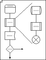
Use Specification and Description Language (SDL) shapes, designed to International Telecommunications Union standards, to create object-oriented flowcharts that document communications and telecommunications systems networks.
-
Start Visio.
-
In the Flowchart template/category, click SDL Diagram and then click Create.
-
For each step in the process you are documenting, drag a flowchart shape onto your drawing.
-
Connect the shapes.
-
Drag a shape from a stencil onto the drawing page and position it near another shape.
-
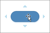
Hold the pointer over the shape until AutoConnect arrows appear around the shape.
-
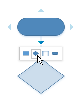
Hold the pointer over the arrow in the direction you want to add a shape.
A mini toolbar appears that contains the first four Quick Shapes that are currently in the Quick Shapes stencil. When you point at a shape on the toolbar, Visio displays a preview of that shape on the page. What is Quick Shapes?.
-
Click the shape you want to add.
The shapes are now connected.
-
-
To add text to a shape, select it, and then type. When you are finished typing, click outside the text block.
-
You can number the shapes in your flowchart to illustrate the sequence of process steps.
-
In a flowchart, select the shapes you want to number.
-
On the View tab, click Add-Ons > Visio Extras > Number Shapes.
-
On the General tab, under Operation, click Auto Number. Under Apply To, click Selected Shapes, and then click OK.
Tip: To automatically number new flowchart shapes as they are dragged onto the page, in the Number Shapes dialog box, click Continue numbering shapes as dropped on page.
-

