

Use the Floor Plan template in Visio to draw floor plans for individual rooms or for entire floors of your building―including the wall structure, building core, and electrical symbols.
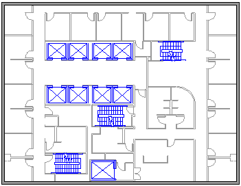
Here is an example of a completed floor plan.
Start a new floor plan
- In the Categories list, select the Maps and Floor Plans category.
- Select Floor Plan, and then select Create.
Turn on gridlines to help with scale and precision
You may want to have gridlines visible on your drawing canvas to help you lay out and scale objects carefully:
- On the toolbar ribbon, select View > Grid.
A fixed grid can be useful in floor plans and maps, where you always want grid lines to show the same measurement. To make the grid fixed:
- On the toolbar ribbon, select View.
- In the right corner of the Show group, select the "More" arrow
 .
. - In the dialog box, enter the minimum spacing required between lines for each axis, and the grid will retain a fixed perspective throughout your design process, regardless of zoom level.
Create the exterior wall structure
Using room shapes
- From the Walls, Shell and Structure stencil, drag one of the room shapes onto the drawing page.
- Resize the room shape by dragging the control and selection handles on individual walls.
Using wall shapes
From the Walls, Shell and Structure stencil, drag Exterior wall shapes onto the drawing page.
Continue to draw the exterior by using these options:
- Resize walls by dragging an endpoint.
- Right-click wall shapes to set options.
- Drag an endpoint of one wall to another wall.
The endpoints are highlighted when the walls are glued. Intersections between two walls are cleaned up automatically.
Create the interior wall structure
From the Walls, Shell and Structure stencil, drag wall shapes onto the drawing page, positioning them inside the exterior structure.
Continue to draw the interior by using these options:
- Resize walls by dragging an endpoint.
- Right-click a wall to set options.
- Drag an endpoint of one wall to another wall.
Add doors and windows
- From the Walls, Shell and Structure stencil, drag door and window shapes on top of walls.
Doors and windows automatically rotate to align with and glue to the wall. They also acquire the wall's thickness and move with walls when you reposition them.
Add other structural elements
- From the Walls, Shell and Structure stencil, drag structural shapes, such as columns, onto the drawing page.
- From the Building Core stencil, drag building core shapes, such as stairs, onto the drawing page.
Add electrical symbols and dimension lines
Electrical symbols
- From the Electrical and Telecom stencil, drag wall switches, outlets, and other wall fixtures onto wall shapes. Release the mouse button when a bold square appears, which indicates that the symbol is glued to the wall. Wall fixtures automatically rotate to align with and glue to the wall.
Dimension lines for walls
- Right-click a wall, and then select Add a Dimension.
- Reposition the dimension lines and text by dragging a control handle.
If you want to resize a wall after you add a dimension to it, select the dimension shape, type the dimension you want, and then select away from the dimension shape.
Insert a CAD floor plan
- On the Insert tab, select CAD Drawing.
- Select the DWG or DXF file, and then select Open.
- In the CAD Drawing Properties dialog, confirm the drawing scale and page placement. If you need to preserve the AutoCAD scale, match the CAD drawing scale to the viewport scale.
- If necessary, configure the layers to import, and then select OK.
After inserting the drawing, you can change its scale or layer properties. If the drawing is locked, unlock it before moving, resizing, or deleting it.
Save as a DWG file
DWG is a commonly used CAD drawing format. Saving the diagram as a DWG file allows it to be opened in compatible CAD applications. If the Visio file contains multiple drawing pages, save each page as a separate DWG file.
- On the File tab, select Save As > Browse.
- Change the Save as type to AutoCad Drawing (.dwg).