
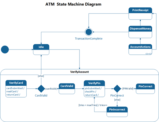
You can create a UML state machine diagram to show the behavior of a part of a designed system.
How an object responds to an event depends on the state that object is in. A state machine diagram describes the response of an object to outside stimuli. The object can be a computer program, device, or process.
First, you open the UML State Machine diagram that comes with a state machine stencil that has shapes that conform to the UML 2.5 or 2.0 standard, depending on your version of Visio.
- Start Visio. Or if you have a file open already, click File > New.
- In the Search box, type
UML state machine. - Select the UML State Machine diagram.
- In the dialog box, select the either Metric Units or US Units.
- Select Create.
- The diagram opens. You should see the Shapes window next to the diagram. If you don’t see it, go to View > Task Panes and make sure that Shapes is selected. If you still don’t see it, click the Expand the Shapes window button on the left.
- On the View tab, make sure the check box next to Connection Points is selected. This will make connection points appear when you start connecting shapes.
- Now, drag shapes you want to include in your diagram from the Shapes window to the page. To rename text labels, double-click the labels.