Bỏ qua để tới nội dung chính
Đăng nhập với Microsoft
Đăng nhập hoặc tạo một tài khoản.
Xin chào,
Chọn một tài khoản khác.
Bạn có nhiều tài khoản
Chọn tài khoản bạn muốn đăng nhập.
Tiếng Anh
Chúng tôi rất tiếc. Bài viết này không có bằng ngôn ngữ của bạn.

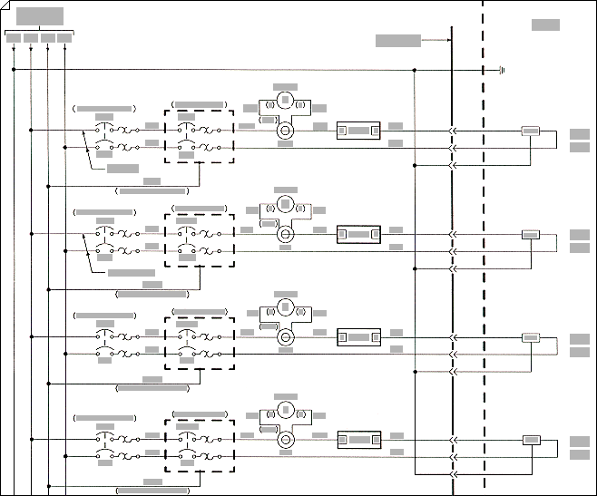
Use the Electrical Engineering drawing type in Visio Professional or Visio Plan 2 to create electrical and electronic schematic diagrams.

Electrical engineering circuit

  1. On the File tab, select New, and then search for Engineering templates.

  2. Select one of the following:

    • Basic Electrical

    • Circuits and Logic

    • Fluid Power

    • Industrial Control Systems

    • Parts and Assembly Drawing

    • Piping and Instrumentation Design

    • Plumbing and Piping Plan

    • Process Flow Diagram

    • Systems

    • TQM diagram

    • Work Flow Diagram

  3. Choose Metric Units or US Units, and then select Create.

    The template opens an unscaled drawing page in portrait orientation Tall page. You can change these settings at any time.

  4. Drag electrical component shapes onto the drawing page. Shapes can have data. You can enter shape data and add new data to a shape.

    Enter shape data

    1. Select a shape, right-click, select Data, and then select Define Shape Data.

    2. In the Define Shape Data dialog box, select in each item and type or select a value.

  5. Use the Connector tool Button image to connect electrical components or connector shapes.

    Use the Connector tool

    1. Select the Connector tool Button image.

    2. Drag from a connection point Connection point image - blue X on the first shape to a connection point on the second shape. The connector endpoints turn red when the shapes are connected.

    Use connector shapes

    1. Drag a connector shape onto the drawing page.

    2. Place the connector's begin point Begin point image - green square with X inside on the parent shape (the shape you’re connecting from).

    3. Place the connector's end point End point image, which is plus sign in a green square on the child shape (the shape you’re connecting to).

      When the connector is glued to the shapes, the endpoints turn red.

  6. Label individual electrical component shapes by selecting the shape and typing.

Want More?

Find sample electrical engineering Visio templates and diagrams

Bạn cần thêm trợ giúp?

Bạn muốn xem các tùy chọn khác?

Explore subscription benefits, browse training courses, learn how to secure your device, and more.

Communities help you ask and answer questions, give feedback, and hear from experts with rich knowledge.

Thông tin này có hữu ích không?

Điều gì ảnh hưởng đến trải nghiệm của bạn?
Khi nhấn gửi, phản hồi của bạn sẽ được sử dụng để cải thiện các sản phẩm và dịch vụ của Microsoft. Người quản trị CNTT của bạn sẽ có thể thu thập dữ liệu này. Điều khoản về quyền riêng tư.

Cảm ơn phản hồi của bạn!

×